STAGE RACER
12, 8 or 4 SDI 3G, 1 G/L, 16 audio I/O, 2AES/1MADI, 2 IP, 4 RS, 8 GPIO
Overview
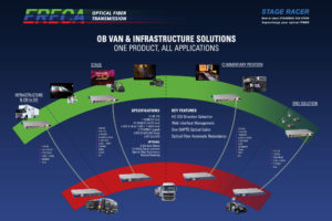
The STAGE RACER product line is an ultra flexible solution to connect a stage to an OB VAN.
With the ERECA unique feature for on the fly direction configurable HDSDI channels and the numerous commodities signal transmitted along the videos, the stage racer is the product of choice for an affordable fast and easy event deployment.
The equipment assumes transmission of a comprehensive set of signals as follows:
- 12, 8 or 4 video 3G / HD / SDI signals (direction configurable through built in web server),
- 1 Genlock bidirectional (PAL image / Black burst / Tri-level),
- 16 analog audio I/O for intercom or broadcasting,
- 2 Ethernet 10/100/1000Mbs (1 Gigabit trunk with 2 VLANS),
- 4 Data RS 232/422/485,
- 8 Contact closures.
- 4 AES 3 bidirectional (Riedel panel compatible)
- 1 bidirectional MADI (AES10) Signal (Shared with 2 of the 4 AES connectors).
All the signals are transmitted on 2 singlemode fibers. As an option, an optical cable failover is built inside the modules by adding a second connector. In case of fiber break the equipment automatically select the other cable.
Connectivity
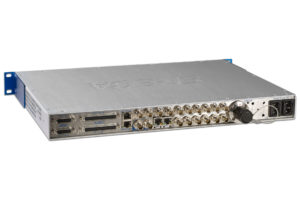
Standard connectors are used for all the signals. HD and PAL video ports are on BNC connectors.
The other connectors are RJ45 / D SUB.
Optical and remote power access is done through a Neutrik OpticalCon DUO or LEMO 3K socket.
Signaling / Web browser
Each equipment has a LED display panel for signal presence and alarm display.
An internal web server enables remote management and setup (signal presence report / optical power measurement / Data settings / Configure direction of each HD video signal).
Standard specifications
Optical
| Dynamic range: | 7 dB (~ 15Km) |
| Connector: | NEUTRIK OpticalCon DUO or LEMO 3K (EDW / FXW) |
Video SD/HD
| Number, connector: | 3 versions: 12, 8 or 4 channels on BNC (Each signal direction configurable). |
| Direction setting | Internal Web Server. |
| Impedance: | 75 Ω |
| Standard: | SDI, ASI, HD, 3G |
| Amplitude: | Input: cable equalization (140 m Belden 1694A for 3G), Output: 800mV pp |
| Return loss: | Better than – 15 dB for 0 to 1500Mhz and better than – 10 dB for 1500 to 3000Mhz |
Analog Video / GL
| Number, connector: | 1 Bidirectional, 2 BNC |
| Standard: | PAL, SECAM, NTSC, Tri-level ( Bi / Tri level auto sense ) |
| Impedance: | 75 Ω |
| Bandwidth: | > 5.8 MHz at +/- 0.2dB |
| Differential Gain/ Phase | < 1%, < 1° |
| Group delay: | < 10 ns |
| SNR: | > 67 dB (CCIR567) |
Analog Audio
| Number, connector: | 16 line inputs Sub-D37, 16 line outputs Sub-D37 / Mic option available (cf below) |
| Impedance: | Input: 10 KΩ differential (non floating), Output: 20 Ω differential (non floating) |
| Amplitude: | +4 dBm nominal (saturation at + 18 dBm) |
| Bandwidth: | 50 Hz to 15 KHz at +/- 0.5dB, (20Hz to 20 Khz at -3dB) |
| Distortion: | 0.05% at 1Khz +18 dBm |
| Signal to noise ratio: | 90dB, “A” weighted |
Digital audio
| Number, connector | 4 AES bidirectional (Riedel panel compatible) OR 1 MADI (AES10) + 2 AES bidirectional (Riedel panel compatible) |
| Bitrate | Up to 48Khz AES audio / 125MBs full bandwith for MADI |
| Impedance / Connector: | 75 Ω, BNC |
| Setting: | Internal Web Server. |
Data
| Number, connector: | 4 bidirectional channels, 1 RJ 45 socket per channel (2 internal connectors for customer custom). |
| Protocols: | RS485, RS422, RS232 |
| Data rate: | 0 to 230 Kbd/s |
| Setting: | Internal Web Server. |
Ethernet
| Number, connector: | 2 channels on VLAN, RJ45 Socket |
| Protocols: | 10, 100 or 1000 mb/s, Full or Half-duplex (Auto), MDI or MDI-X (Auto) |
GPIO
| Number, connector: | 8 bidirectional GPIO contacts / 6 on D-SUB plus 1 GPIO along each DATA RJ45 connector |
| Output: | Relay (dry contact). ‘Common’ – ‘Normally Open’ terminals for each relay |
| Input: | Floating on the D-SUB, Input pin grounding on RJ45. |
Powering
| Consumption: | 20 Watts per side |
| Low voltage source: | 8 to 16 V DC, XLR 4 pins connector, protected by 5*20 mm standard internal fuse |
| Mains source: | From 90 to 260 VAC / 47 to 63 Hz Dual supplies in the 1U rack |
| Hybrid cable source: | From 24 to 48 volts on powered device input / allowing 500m of AWG16 cable. |
Mechanical
| Rack model: | 1 RU 19” rack, depth 300mm excluding connectors. |
| Cooling: | Internal fan / (Case walls acting as Heat sink / No dust entry guarantee for the RUGGED ) |
| Operating Temp range: | From -20 to + 60°C. (Avoiding direct sun exposition) |
Signaling / Setup
| Transmitted signals: | 1 LED per signal |
| Alarms | 1 LED per technical alarm (Power supply / Temperature / Fiber alarm ) |
| Remote | All signal presence / alarm are reported trough the web server. |
| Settings | All settings are done trough the web server. |
Optional modules specifications
Optical Redundancy module
| Redundant path: | Double optical transmission with automatic optical path selection. |
| Optical losses: | 1.8 dB per link for optical switching |
Analog Audio Mic Preamp module
| Input: | Microphone input gain block on 8 of the 16 channels |
| Mic input, Gain: | From 10 to 60 dB, Bypass and Tunable by 3 dB steps, through internal Web Server. |
| Phantom power: | 48 volts switchable, through internal Web Server, Source Impedance 6.8 KΩ |
Additionnal Serial Data module
| Number, connector: | 12 bidirectional channels, one SUB D 25 for 6 channels (1U rack version). |
| Protocols: | RS422 |
| Data rate: | 0 to 19.2 Kbd/s |
Remote Powering module on Lemo 3K
| Power topology: | Power source: 1U rack STAGE RACER Powered device: Rugged STAGE RACER box |
| Camera powering: | 12VDC, 30 W available on XLR 4 |
| Performance with AWG16 SMPTE cable: | 2.5 km for rugged STAGE RACER box alone (no camera remote powered) 950 m for rugged STAGE RACER box + 30W camera load |
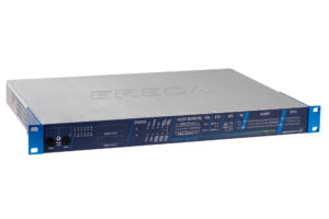
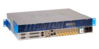
- Ereca Stage Racer front
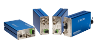
- Ereca Stage Racer back
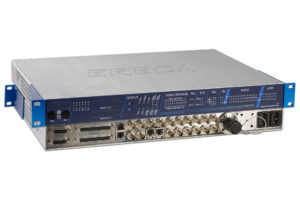
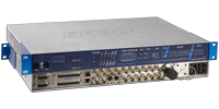
- Ereca Stage Racer front & back superposed
- Applications Panel Stage Racer
