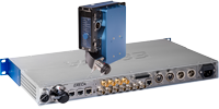
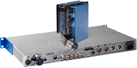
CAM RACER 4K
Dockable optical fiber transmission unit with 2x12G + 2x3G SDI for ENG up to 4K cameras
Overview
The CAM RACER 4K is a complete optical fiber transmission solution for camera connection for Outside Broadcast, Studio and Cinema applications. It is composed of a camera dockable transmitter, agnostic to any type or brand of Camera and a 1RU basestation receiver.
Highlights
With two 12G-SDI and two 3G-SDI channels, the CAM RACER 4K can fit any camera from simple ENG to 4K Live sport devices making it suitable for any environment and ideal for rentals.
CAM RACER 4K delivers 140 Watts to the camera. An automatic battery backup will help the remote powering system if more power is needed suddenly.
Signals control and Setup is done through internal web server. Most signals are also reported on LED display of each unit. An Oled display gives direct access to optical receiving levels and server IP address.
An internal audio mixer allows user to mix between talkback, programs inputs and local audio channels for Eng and Reporter headsets.
Camera control channel supports: Ethernet, RS422 Serial, Canon RC-V100 protocol (Enhanced Lanc).
Camera synchronization supports: Two composite video signals and one timecode.
Detailed description
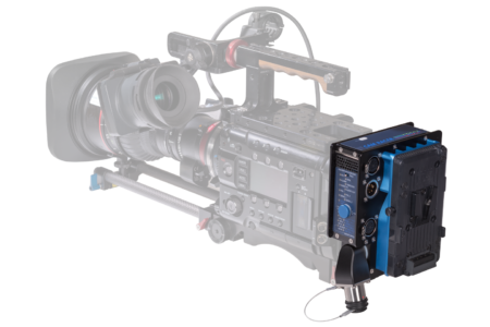
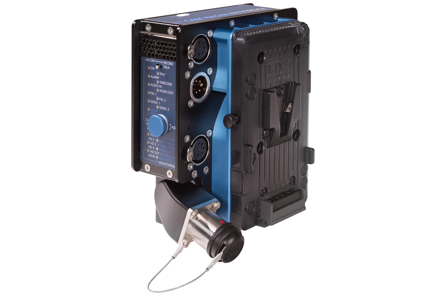
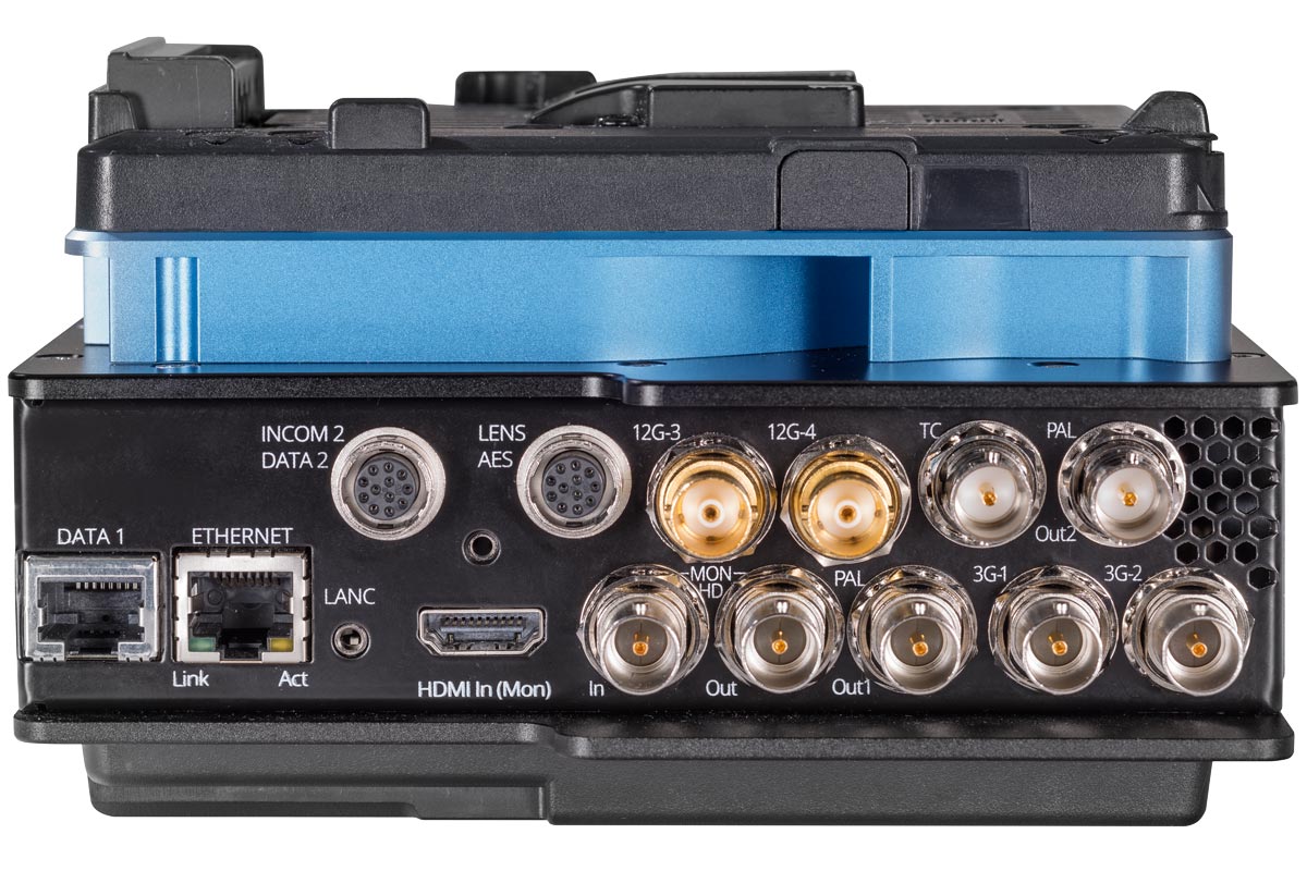
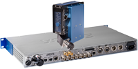
The transmitter is fitted in a V-mount dockable unit which can be installed on any camera.
Red/green tally led are located on top of the unit.
A user panel feature LEDs for signal presence/activity, rotary button for volume adjustment and various level settings (sidetone, program1 / program2 listen level) along with push to talk commands.
Cooling of the unit is done by a small and silent fan located at the back of the unit.
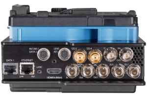
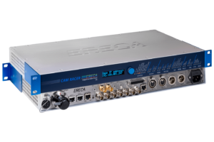
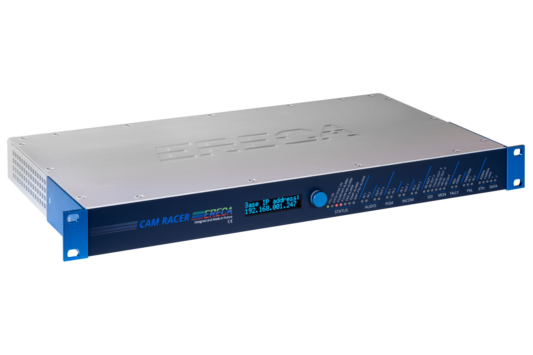
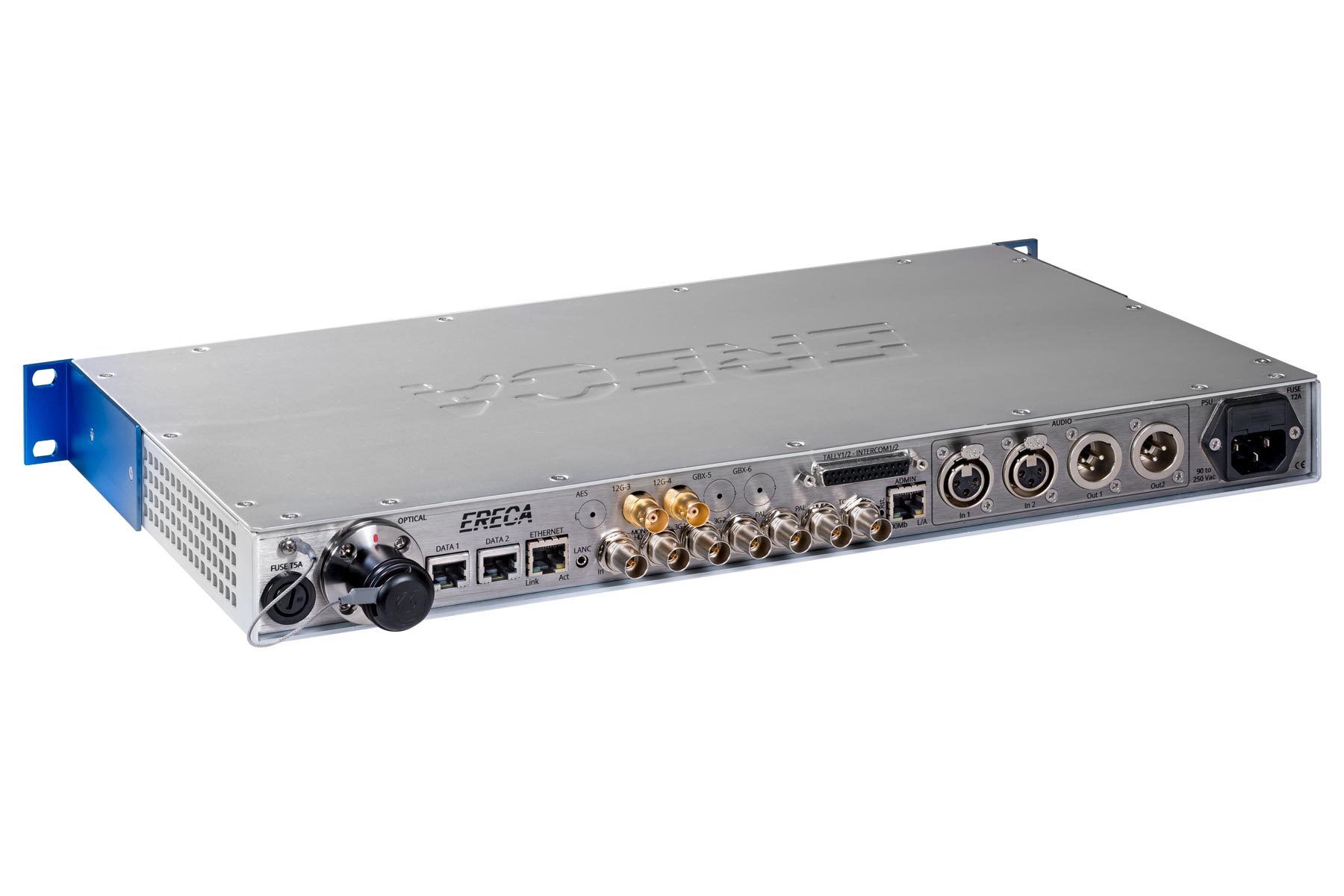
The basestation receiver is integrated in a standard 19” 1RU format. All signals are dispatched on standard connectors and standard pinout at the rear of the chassis. (Web server is on a separate Ethernet port).
The front of the chassis is composed of a LED display panel indicating the status of each signals and technical alarms. An Oled display gives direct access to optical receiving levels and server IP address.
The basestation integrates a single mains power supply and two fans for thermal management.
Electrical Interfaces
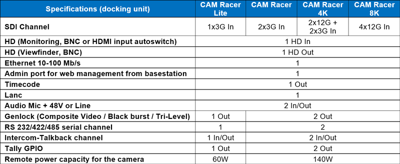
There are 4 standard configurations of CAM Racer.
Each equipment assumes transmission of a comprehensive set of signals as follows:
| CAM Racer Lite | CAM Racer | CAM Racer 4K | CAM Racer 8K | |
| Optical | ||||
| Dynamic range: | 15 dB for control, 10dB for 12G channels | |||
| Connector: | LEMO 3K (EDW / FXW) or NEUTRIK OpticalCon DUO | |||
| SDI Video HD to 12G | ||||
| Number: | 1x3G | 2x3G | 2x12G + 2x3G | 4x12G |
| Connector: | 3G certified 75Ω BNC | 3G & 12G certified 75Ω BNC | ||
| Standard: | HD, 3G | HD, 3G, 6G, 12G with 12G channels board | ||
| Amplitude: | Input: cable equalization on all channels including 12G, Output: 800 mV pp / reclocked | |||
| Return loss: | Better than: -15 dB for 0 to 1.5 Ghz, -10 dB for 1,5G to 3G, -6dB for 3G to 12G | |||
| Composite Video / GL | ||||
| Number, connector: | 1 x 75Ω BNC from RX to TX | 2 x 75Ω BNC from RX to TX | ||
| Standard: | Composite video, Black Burst, Tri-level (Bi / Tri level auto sense) | |||
| Performance: | BW > 5.8 MHz at +/- 0.2 dB, DgDp < 1%, < 1°, Group delay < 10 ns, SNR > 67 dB (CCIR567) | |||
| Analog Audio | ||||
| Number, connector: | 2 bidirectional channels, XLR 5pins on camera unit, XLR 3pins on base station | |||
| Impedance: | Input: 10 KΩ differential (non-floating), Output: 20 Ω differential (non-floating) | |||
| Amplitude: | +18 dBm maximum | |||
| Bandwidth: | 50 Hz to 15 KHz at +/- 0.5dB, (20 Hz to 20 KHz at -3 dB) | |||
| Distortion: | 0.05% at 1Khz / 0 dBm | |||
| Signal to noise ratio: | 90dB, “A” weighted | |||
| Mic input | ||||
| Input: | Microphone input gain block on the camera unit | |||
| Mic input, Gain: | From -12 to 40 dB, Tunable by 1 dB steps, Totally by-passable | |||
| Phantom power: | 48 volts switchable, Source Impedance 6.8 KΩ | |||
| Timecode | ||||
| Number, connector: | 1 from basestation to camera unit, 75Ω BNC | |||
| LANC | ||||
| Number, connector: | 1 bidirectional, Jack2.5mm | |||
| Protocol | Standard LANC or RC-V100 remote protocol (5V open collector signaling) | |||
| Data | ||||
| Number, connector: | 1 bidirectional channel, RJ45 | 2 bidirectional channels, RJ45 for Ch1, Hirose 12 for Ch2 | ||
| Protocols, Data rate: | RS485, RS422, RS232 from 0 to 500 Kbd/s | |||
| Ethernet | ||||
| Number, connector: | 1 channel, RJ 45 | |||
| Protocols: | 10 or 100 Mb/s, Full or Half-duplex (Auto sense), MDI or MDI-X (Auto sense) | |||
| Intercom / Tally | ||||
| Number: | 1 Tally, 1 Intercom | 2 Tally, 2 Intercom | ||
| Tally output: | Relay (dry contact) shared with serial RJ45 (red) and Hirose 12 (green). Red/Green LED | |||
| Tally input: | Contact or Voltage input. Shared on intercom D-SUB 25 pins with standard CCU pinout | |||
| Camera Intercom I/O: | Any type of Headset Mic (Dynamic, Electret, Static) and Earpiece impedance (20 to 600 Ohms) | |||
| Basestation Inter. I/O: | Line levels for Intercom and program input | |||
| Talk command: | Pushbutton on cam unit, PTT input on RJ45 for pocket PTT switch (Talk latch release on basestation) | |||
| Connector: | XLR 5 pins (intcom1), Hirose 12 pin (intcom2), Standard D SUB 25 pins on base (Tally, Intcom, PGM) | |||
| Power section | ||||
| Camera unit: | 7 Watts for 2x3G basic device + Additional 3W for dual 12G channel option | |||
| Camera power capacity
(Standard 9.2mm SMPTE) |
14.4V, 60W continuous | 14.4V, 140W continuous, temporary unlimited with automatic battery backup. Decreasing for length over 450m (100W at 600m). | ||
| Battery plates: | V-Lock or Anton Bauer | |||
| Basestation unit: | 10 VA for the basestation (Additionally up to 200VA for remote power source) | |||
| Mains source base: | From 90 to 260 VAC / 47 to 63 Hz | |||
| Mechanical | ||||
| Camera unit: | 155 * 145 * 44mm excluding connectors & plates (Add 13mm for power converter), weight 1,4kg | |||
| Basestation: | 1 RU 19” rack, depth 250mm excluding connectors, weight 3kg | |||
| Operating Temp range: | From -20 to + 60°C. (Avoiding direct sun exposition) | |||
- CAM Racer TX (front with Vlock & Lemo)
- CAM Racer RX (front)
- CAM-Racer mounted Vlock
- CAM Racer 4K TX (back)
- CAM Racer 4K RX (back)
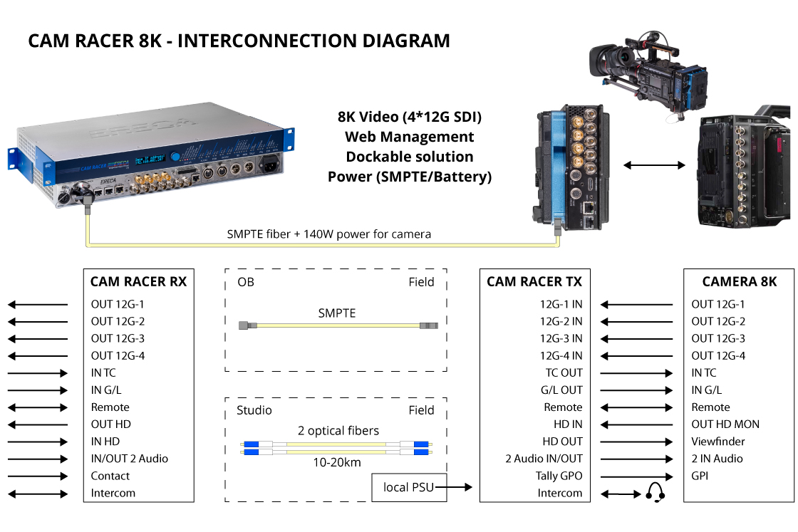
- CAM Racer 8K Interconnection Diagram
